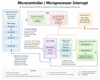
In Parts 1 through 3 we learned what interrupts are, how to write safe ISRs, and how to use timer interrupts for precise periodic tasks. So far we have treated interrupts as if only one can exist at a time. In reality, a microcontroller may have dozens of interrupt sources, and several of them can become active at the same moment. This raises an important question: when two interrupts fire at the same time, which one runs first? And what happens if a second interrupt fires while an ISR is already running? The answers lie in interrupt priority systems and a concept called interrupt nesting.
Why Priority Matters: A Real-World Scenario
Imagine a medical device that does three things simultaneously:
- Monitors a patient’s heart rate via a sensor pin (critical — must never be missed).
- Updates a display every 500 milliseconds (important but not life-critical).
- Logs data to an SD card every 5 seconds (low urgency).
If the SD card logging interrupt and the heart rate interrupt fire at exactly the same time, you absolutely need the heart rate interrupt to be handled first. If the SD card ISR is already running when the heart rate interrupt fires, you need the processor to pause the SD card ISR, handle the heart rate interrupt immediately, and then return to the SD card ISR. That is interrupt nesting driven by priority.
Without a priority system, the processor would handle interrupts in an arbitrary or fixed order, and critical events could be delayed by unimportant ones. Priority systems exist to prevent exactly this.
The Two Key Concepts
Interrupt Priority
Every interrupt source is assigned a priority level — a number that indicates its urgency relative to other interrupts. When two interrupts are pending at the same time, the one with the higher priority runs first. What “higher priority” means numerically varies by platform: on STM32 and ARM Cortex-M devices, a lower number means higher priority (0 is the most urgent). On PIC18, a simpler high/low two-level system is used.
Interrupt Nesting
Nesting means that a higher-priority ISR can interrupt a currently running lower-priority ISR. The processor saves the state of the interrupted ISR, runs the higher-priority one to completion, then returns to the lower-priority ISR and finishes it. Without nesting enabled, an ISR runs to completion before any other ISR can start — even a more urgent one.
The ARM Cortex-M NVIC: The Most Capable System
The Nested Vectored Interrupt Controller (NVIC) is a hardware block built into all ARM Cortex-M processors — the core used by STM32, many ESP32 variants, some MSP432 devices, and many others. It is the most sophisticated interrupt priority system you will encounter in the microcontroller world, and understanding it well gives you a foundation that transfers across many platforms.
Key features of the NVIC:
- Supports up to 240 external interrupt sources (the exact number depends on the chip).
- Each interrupt has a configurable priority from 0 (highest) to 255 (lowest), though most chips implement fewer bits — STM32 typically uses 4 bits, giving 16 priority levels (0–15).
- Nesting is automatic: a higher-priority interrupt always preempts a lower-priority one.
- Hardware saves and restores CPU state automatically on interrupt entry and exit (no manual context saving needed).
- Supports a basepri register to mask all interrupts below a certain priority threshold without disabling all interrupts globally.
Priority Grouping on STM32
STM32 adds one more layer on top of the basic NVIC priority: it splits each priority value into two sub-fields called preemption priority and sub-priority.
- Preemption priority determines whether one ISR can interrupt another. A lower preemption priority number can preempt a higher number.
- Sub-priority only matters when two interrupts of equal preemption priority are pending at the same time. It determines which one runs first, but it does not allow nesting between them.
The split between these two fields is controlled by the priority group setting. CubeMX sets this to group 4 by default, which gives 4 bits of preemption priority and 0 bits of sub-priority — meaning 16 preemption levels and no sub-priority. This is the most common and simplest configuration.
// Setting interrupt priorities in STM32 HAL
// Lower number = higher priority (more urgent)

// Heart rate sensor on EXTI Line 0 — highest priority
HAL_NVIC_SetPriority(EXTI0_IRQn, 0, 0);
HAL_NVIC_EnableIRQ(EXTI0_IRQn);

// Display update timer TIM2 — medium priority
HAL_NVIC_SetPriority(TIM2_IRQn, 8, 0);
HAL_NVIC_EnableIRQ(TIM2_IRQn);

// SD card SPI — lowest priority
HAL_NVIC_SetPriority(SPI1_IRQn, 15, 0);
HAL_NVIC_EnableIRQ(SPI1_IRQn);
With this configuration, if the SPI ISR is running and the heart rate EXTI fires, the NVIC will automatically suspend the SPI ISR, run the EXTI ISR to completion, and then resume the SPI ISR. This happens in hardware with no software intervention required.
A Complete STM32 Priority Nesting Example
Here is a more complete demonstration showing how priorities interact in practice:
// Assume CubeMX has generated init code for TIM2, TIM3, and EXTI0

volatile uint32_t heartRateCount  = 0;
volatile uint32_t displayTicks    = 0;
volatile uint32_t logTicks        = 0;

// EXTI0 ISR — priority 0 (highest) — can preempt everything
void EXTI0_IRQHandler(void) {
    HAL_GPIO_EXTI_IRQHandler(GPIO_PIN_0);
}

void HAL_GPIO_EXTI_Callback(uint16_t GPIO_Pin) {
    if (GPIO_Pin == GPIO_PIN_0) {
        heartRateCount++;   // Count pulse — fast and safe
    }
}

// TIM2 ISR — priority 8 — can preempt TIM3 but not EXTI0
void HAL_TIM_PeriodElapsedCallback(TIM_HandleTypeDef *htim) {
    if (htim->Instance == TIM2) {
        displayTicks++;     // Signal display update needed
    }
    if (htim->Instance == TIM3) {
        logTicks++;         // Signal logging needed
    }
}

// In main loop — all heavy work done here, ISRs just set flags/counters
while (1) {
    if (displayTicks > 0) {
        displayTicks = 0;
        updateDisplay(heartRateCount);
    }
    if (logTicks > 0) {
        logTicks = 0;
        logDataToSD(heartRateCount);
    }
}
Note that TIM3 would be configured with a lower priority than TIM2 in HAL_NVIC_SetPriority(). The NVIC handles all the preemption automatically.
One Critical STM32 Rule: FreeRTOS and Priority
If you use FreeRTOS on STM32, there is a very important rule: any ISR that calls FreeRTOS API functions (such as giving a semaphore from an ISR) must have its priority set to a value equal to or lower (numerically higher) than configLIBRARY_MAX_SYSCALL_INTERRUPT_PRIORITY, which is typically 5. ISRs with priority 0–4 must never call any FreeRTOS functions. Violating this rule causes hard faults that are very difficult to debug. This is one of the most common mistakes when first using FreeRTOS on STM32.
// SAFE: priority 5 or higher number (lower urgency) can use FreeRTOS API
HAL_NVIC_SetPriority(TIM2_IRQn, 5, 0);   // OK to use xSemaphoreGiveFromISR()

// UNSAFE: priority 0-4 must NEVER call FreeRTOS functions
HAL_NVIC_SetPriority(EXTI0_IRQn, 2, 0);  // Cannot use any FreeRTOS API here
Interrupt Priority on Arduino (AVR)
The AVR architecture used in classic Arduino boards (Uno, Nano, Mega) has a much simpler priority system — or more accurately, almost no priority system at all. On AVR:
- There is only a single global interrupt enable bit (the I-flag in the status register).
- When any ISR starts running, the global interrupt flag is automatically cleared, which means all other interrupts are disabled for the duration of the ISR.
- There is no hardware nesting — one ISR cannot interrupt another by default.
- If multiple interrupts are pending when interrupts are re-enabled, the one with the lowest interrupt vector address (hardwired in silicon) runs first. This is a fixed, non-configurable order.
You can manually re-enable interrupts inside an AVR ISR with sei() to allow nesting, but this must be done with extreme care as it can lead to stack overflows if not managed properly.
// AVR: fixed priority order — lower vector address wins
// Vector 1 (INT0, pin 2) always beats Vector 2 (INT1, pin 3)
// No configuration possible — it is hardwired

ISR(INT0_vect) {
    // Running here — all other interrupts are disabled
    // INT1 must wait until this ISR finishes

    // You CAN do this to allow nesting, but be very careful:
    // sei();  // re-enable interrupts — risky on AVR
}
This limitation is one of the main reasons developers move from 8-bit AVR to 32-bit ARM platforms when their applications grow more complex.
Interrupt Priority on ESP32
The ESP32 uses a dual-core Xtensa LX6 processor (or RISC-V on some variants) with its own interrupt matrix — a flexible hardware block that can route any of the 71 peripheral interrupt sources to any of the 32 CPU interrupt inputs, each with its own priority level from 1 to 7.
When using the Arduino framework on ESP32, interrupt priorities are mostly managed for you. However, when using ESP-IDF directly, you can allocate interrupts with specific priorities:
// ESP-IDF lower-level interrupt allocation
// Priority 1 is lowest, priority 7 is highest (NMI level)
// Most application interrupts use priority 1-3

esp_intr_alloc(ETS_GPIO_INTR_SOURCE,
               ESP_INTR_FLAG_LEVEL3,    // Priority level 3
               gpio_isr_handler,
               NULL,
               &gpio_isr_handle);
One unique ESP32 consideration: the two cores can handle interrupts independently. An interrupt can be pinned to a specific core. This is particularly relevant when Wi-Fi and Bluetooth run on Core 0 — keeping your application interrupts on Core 1 avoids interference from the wireless stack.
// Arduino ESP32: pin an interrupt-driven task to Core 1
// to avoid conflicts with Wi-Fi stack on Core 0
xTaskCreatePinnedToCore(
    myTask,       // Task function
    "myTask",     // Name
    10000,        // Stack size
    NULL,         // Parameters
    1,            // Priority
    NULL,         // Task handle
    1             // Core ID (1 = application core)
);
Interrupt Priority on MSP430
MSP430 has a fixed interrupt priority system similar to AVR — priority is determined by the interrupt vector address, hardwired in silicon and not configurable. Lower vector addresses have higher priority. Like AVR, the global interrupt flag is cleared when an ISR starts, preventing nesting by default.
However, the MSP430 compensates for this simplicity with its excellent low-power architecture. Since most MSP430 applications are interrupt-driven with very short ISRs and long sleep periods, the lack of priority configurability is rarely a practical problem.
// MSP430: priority is fixed by vector address in silicon
// RESET_VECTOR is highest priority (always)
// PORT1_VECTOR, TIMER0_A0_VECTOR etc. have fixed relative priorities
// Consult your specific device datasheet for the priority order

#pragma vector=TIMER0_A0_VECTOR
__interrupt void Timer_ISR(void) {
    // Global interrupt flag cleared automatically on entry
    // No other ISR can run until this returns
    // (unless you explicitly re-enable with __bis_SR_register(GIE))
}
Interrupt Priority on PIC18
PIC18 offers the most structured priority system among the 8-bit platforms: a simple but effective two-level system with high priority and low priority interrupts. High priority ISRs can preempt low priority ISRs — giving you one level of nesting.
#include <xc.h>

// High priority ISR — can preempt the low priority ISR
void __interrupt(high_priority) HighISR(void) {
    if (INT0IF) {
        INT0IF = 0;        // Clear flag — mandatory
        // Handle urgent event
    }
}

// Low priority ISR — runs when no high priority ISR is active
void __interrupt(low_priority) LowISR(void) {
    if (TMR1IF) {
        TMR1IF = 0;        // Clear flag — mandatory
        // Handle periodic task
    }
}

void main(void) {
    // Assign INT0 to high priority
    INT0IP = 1;            // 1 = high priority

    // Assign Timer1 to low priority
    TMR1IP = 0;            // 0 = low priority

    // Enable both interrupt levels
    INT0IE = 1;
    TMR1IE = 1;
    PEIE   = 1;            // Peripheral interrupt enable
    GIEH   = 1;            // Enable high priority interrupts
    GIEL   = 1;            // Enable low priority interrupts

    while(1) {
        // Main loop
    }
}
PIC32, Microchip’s 32-bit platform based on MIPS, has a much more capable priority system with 8 priority levels and 3 sub-priority levels — much closer to the STM32 NVIC in capability.
Platform Priority System Comparison
- Arduino AVR: No configurable priority. Fixed order by vector address. No hardware nesting. Simple but limited.
- STM32 (ARM Cortex-M): Up to 16 configurable preemption levels. Full hardware nesting. The most capable system covered here. NVIC is a standard ARM feature transferable across all Cortex-M chips.
- ESP32: 7 priority levels via interrupt matrix. Dual-core adds a spatial dimension — interrupts can be pinned to a core. Highly flexible.
- MSP430: Fixed priority by vector address. No hardware nesting by default. Simple, but the low-power architecture makes this acceptable for most use cases.
- PIC18: Two hardware priority levels with one level of nesting. A practical middle ground for an 8-bit architecture. PIC32 offers much more.
General Advice on Assigning Priorities
When designing a system with multiple interrupt sources, follow these guidelines:
- Assign the highest priority to interrupts that are time-critical and where missing or delaying the event has serious consequences — safety signals, precise pulse counting, hard real-time deadlines.
- Assign medium priority to periodic tasks that need reasonable accuracy — display updates, sensor sampling, communication protocols.
- Assign the lowest priority to housekeeping tasks — logging, non-critical status updates, data that can wait.
- Keep all ISRs short. Priority systems help, but a long high-priority ISR still blocks everything below it for its entire duration.
- On STM32 with FreeRTOS, respect the
configLIBRARY_MAX_SYSCALL_INTERRUPT_PRIORITYboundary religiously. - Test priority interactions deliberately. Fire multiple interrupt sources simultaneously in your test setup and verify the system behaves correctly under load.
What Is Coming in Part 5
With a solid understanding of priority and nesting in hand, Part 5 moves into peripheral interrupts — specifically how UART, SPI, I2C, and ADC peripherals use interrupts to handle data without stalling the CPU. This is where interrupt-driven design really proves its worth in communication-heavy embedded applications, and where you will see how real firmware receives and transmits data reliably at high speed without polling loops.